
Modeling basics
To help you understand the guide, a video is attached at the bottom of the page.
Watching the video along with the guide will make it easier for you to follow along!
STEP 1 : Introduction to Modeling
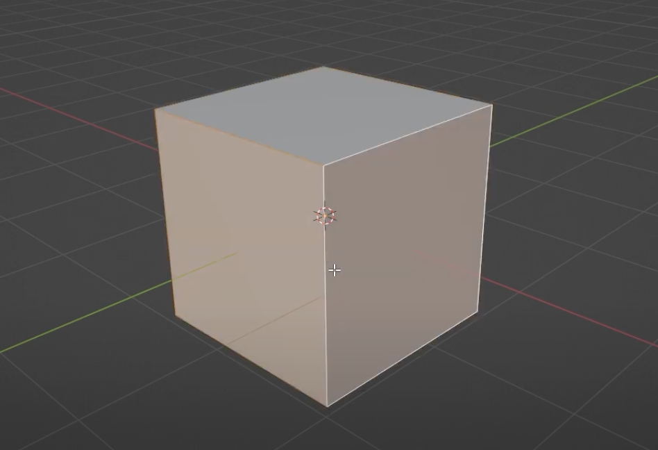
- To learn the basics of modeling, use the Cube object that is set up by default in Blender. Remove the camera and lights from the screen.
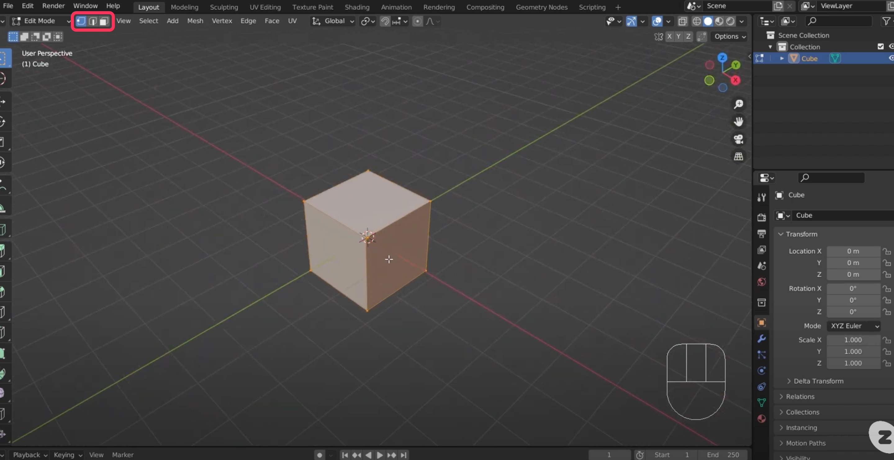
- To begin modeling, you will need to switch to Edit Mode. With the object selected, switch to Edit Mode.
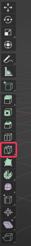
- All Mesh objects are composed of Vertices, Edges, and Faces. You can switch between them with the three buttons in the top left corner of the viewport.
- Vertices - These are simple points in 3D space. They are the core of all three-dimensional objects.
- Edges - An edge is a line that connects two points. They make up the wireframe of an object.
- Faces - A face is a plane made up of three or more points. Faces with three points are called triangles or Tri, faces with four points are called quadrilaterals or Quad, and faces with more points are collectively called N-gons.
STEP 2 : Understanding Tri and Quad
In 3D software, you typically build the faces of an object as triangles or quads. This makes it easier to define how the shape is organized. If an object is built with N-gons, the computer has to interpret them back into tri-forms, which adds an extra layer of complexity.
STEP 3 : Understanding modeling tools
The basics of modeling start with selecting and moving parts in the mesh state.
- By pressing hotkey A to select all vertices, you can move, rotate, or scale the entire object as you would in Object Mode.
- You can move one vertex, or you can hold down Shift and add another vertex to move at the same time.
- To select a loop of vertices, edges, or faces, hold down Alt and click.
A loop means that a full circle is selected based on the selected portion.
- Dragging from an object-free area of the viewport draws a dotted selection box, which you can use to make multiple selections. You can't select occluded areas with the box selection tool.
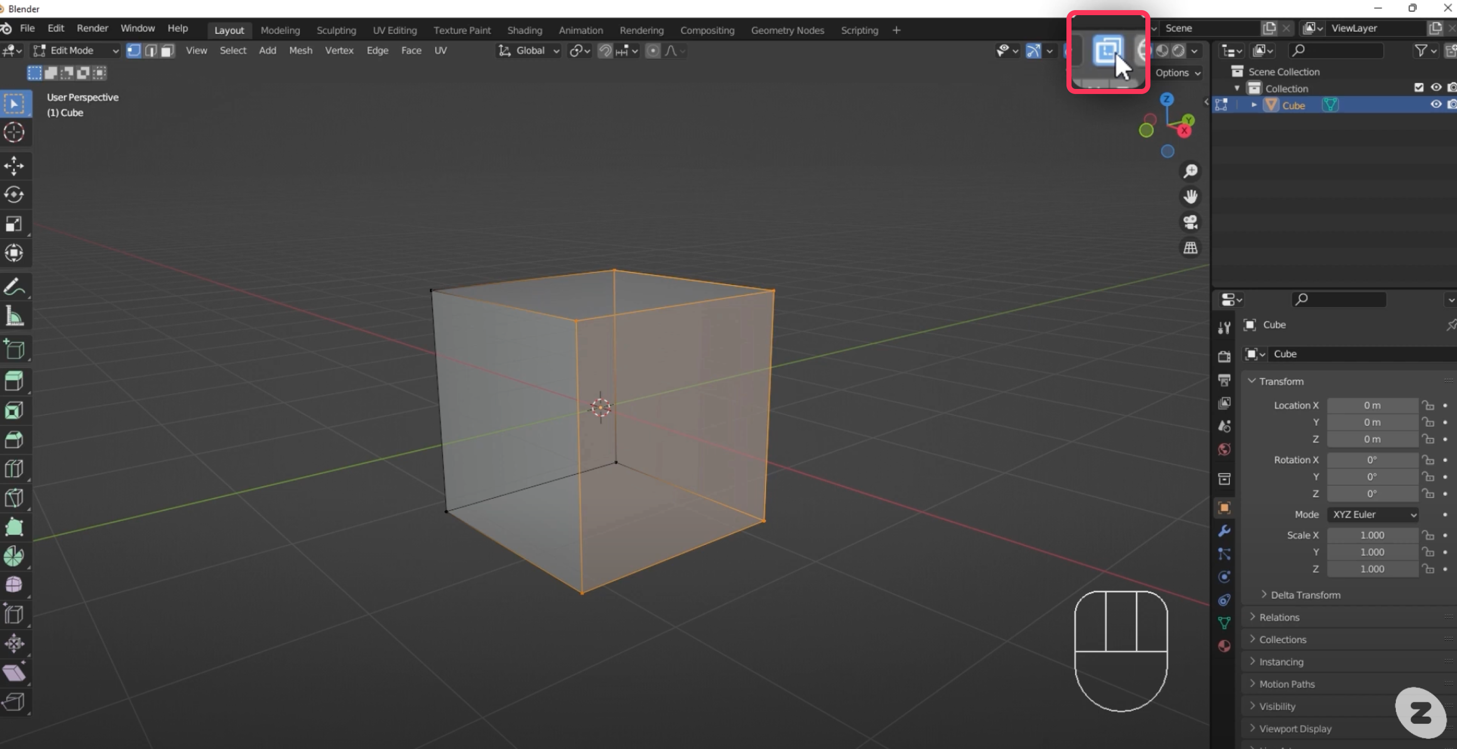
- If you want to be able to select over a box, click the X-ray button in the upper-right corner of the viewport to make the box transparent.
Extending
In addition to adjusting the position of vertices, edges, and faces on basic shapes, you can transform objects by adding new shapes to them.
- Press the keyboard hotkey E or the Expand button in the toolbar.
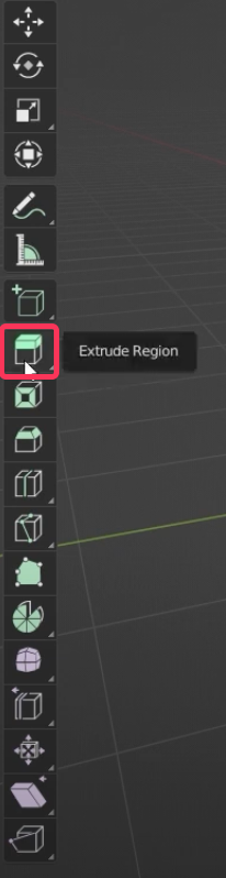
- With the top face button selected, press the face you want to expand and press the Expand button to reveal a gizmo that looks like a +, which you can use to extrude new faces.
- With the top edge button selected, press the edge you want to extend and press the Expand button to extrude a new edge. The same goes for vertices.
Using Loop Cuts
You can add ring loops to add detail to your object.
- Press the keyboard hotkey Ctrl + Ror the Loop Cut button in the toolbar.
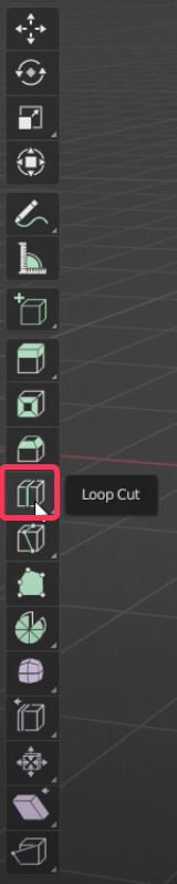
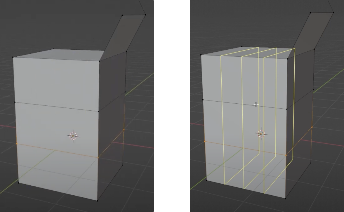
- With the Loop Cut selected, hover over the object to see a highlighted line. Left-clicking on it will create a new edge cut.
- You can also use the scroll wheel in the center of your mouse to increase or decrease the number of cuts.
Using the Knife Tool
This tool allows you to add new edges and vertices by following the basic shape of the object.
- Press the keyboard hotkey Kor the Loop Cut button on the toolbar.
- Select the Knife tool and left-click on the cut edge to preview the new edge in purple. The cut faces will appear in proportion to how they appear on the screen.
- You can right-click to start a new cut.
- To confirm the cut, press the Space bar. To cancel the cut, press the ESC key.
Dismantle or delete a component
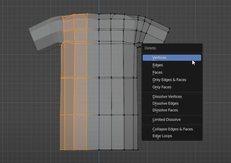
- Delete: Select a component within an object and press the keyboard hotkey X or Delete key to bring up a menu related to deletion.
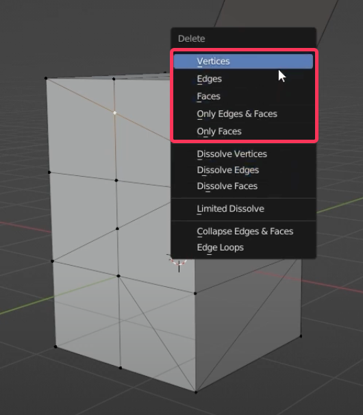
CAUTION!
Deleting a specific part of an object will create a space within the object. This is a feature that you should be very careful with and use with your hand on the undo key(keyboard hotkey Ctrl + Z)
- Dissolve :Selecting a component within an object and pressing the keyboard hotkey X or Delete key will bring up a menu with the option to dissolve it.
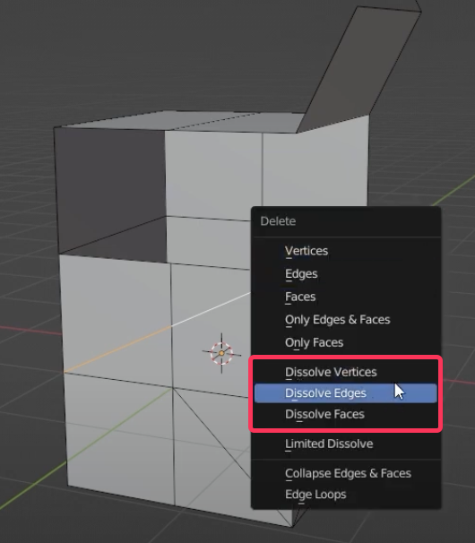
- Dissolve removes only that component, leaving the rest. Dissolve Edges in particular can be very useful for removing unwanted edges.
Merging components
You can merge multiple components. This is a very useful operation to combine individual components together or to improve the flow of an object.
- Select the vertices you want to merge and press the hotkey M or choose the appropriate menu from Mesh > Merge. If you choose At First, the first selected point will be merged.
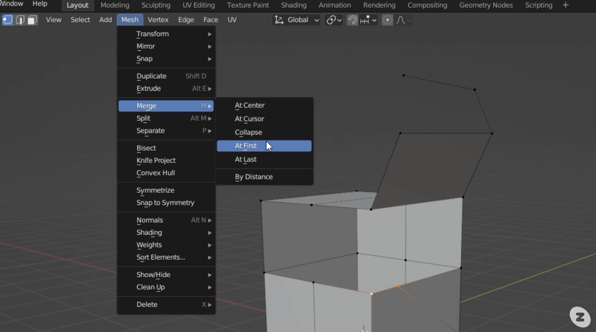
Merging edge loops is useful because it allows you to delete the entire loop. Select the edges and then choose Merge > collapse.
Fill
This tool is used to fill holes in an object. Select two identical components and press the keyboard hotkey F to connect them with a new edge or face.
CAUTION!
It is recommended that you only use the Fill operation on vertices or edges. If you do a fill on a face, the results will be less predictable.
Proportional Editing Features
Moving points one by one to smooth out an object is too much work. When you press the Proportional Editing function button or press the keyboard hotkey O, an operation moves nearby vertices together.
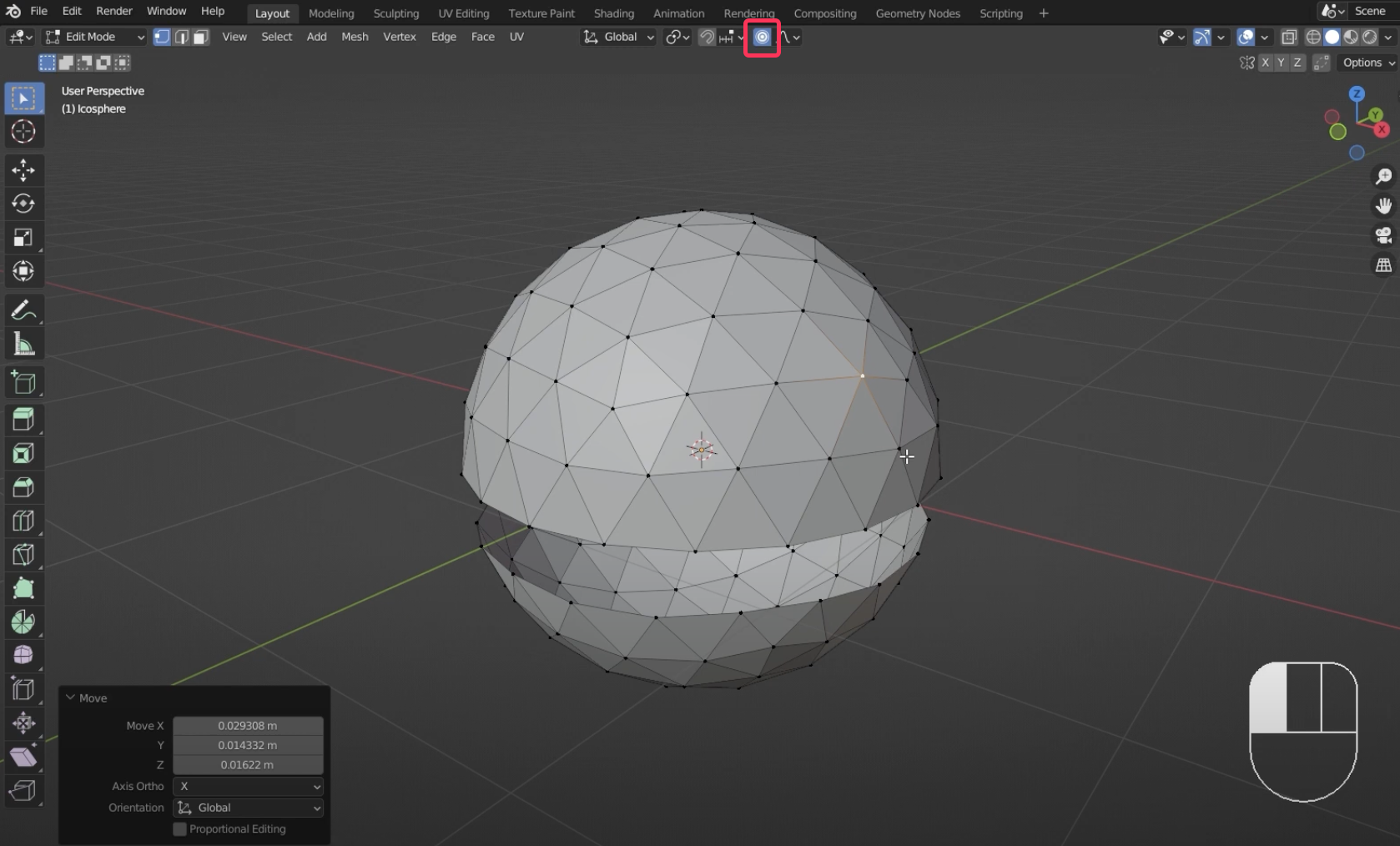
- The affected area is circled in gray. This area can be resized by scrolling the mouse.
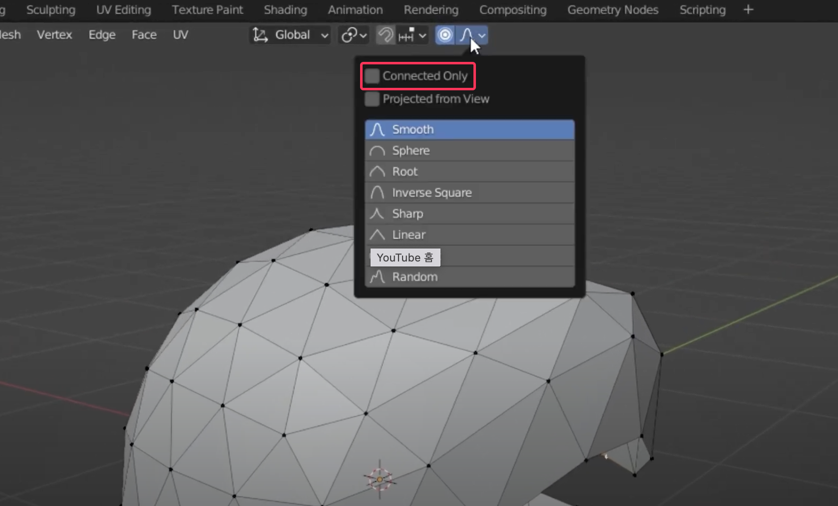
- In the falloff settings menu, you can check the Connected Only button to set only nearby connections to be affected.
Adding other shapes
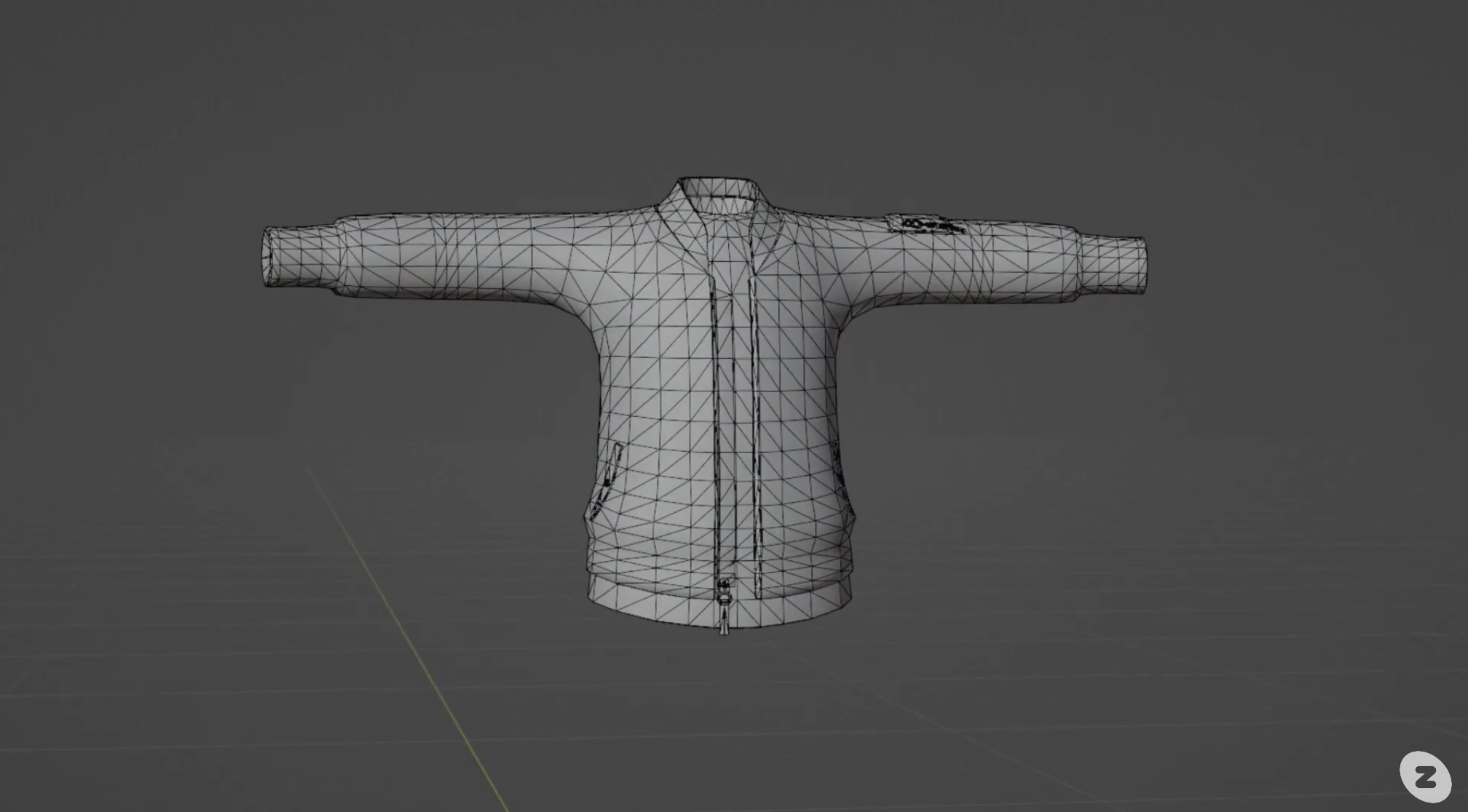
You can also add new shapes to the object you are working on. For example, when creating a top, you might create the body of the object and then add new cylinders to add sleeves.
Modify in mirror mode
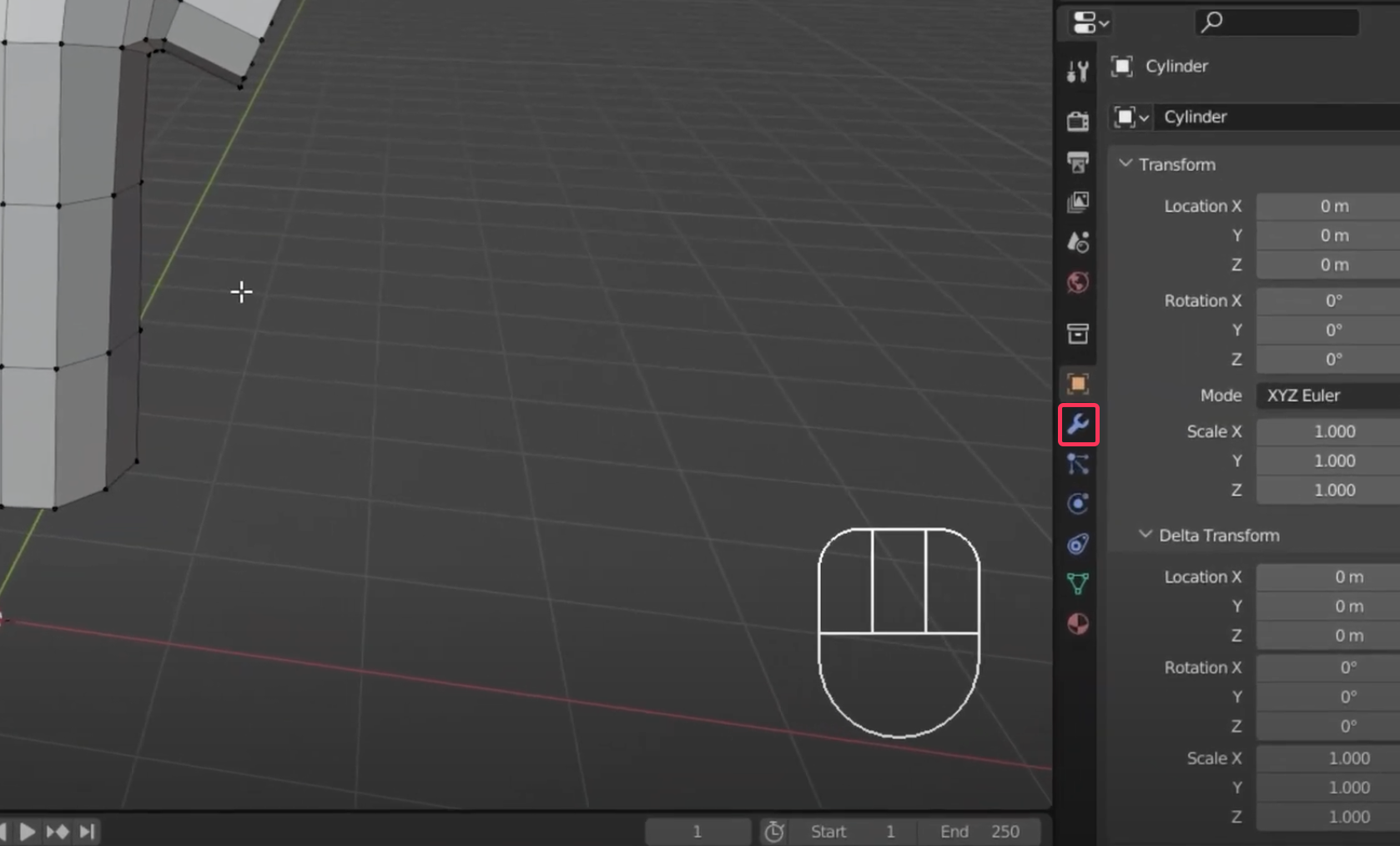
Most garments are horizontally symmetrical. To save you the hassle of having to model both sides, you can use the Modify in Mirror Mode tool. The Modify in Mirror Mode tool is accessed by selecting the spanner-like icon in the bottom left corner.
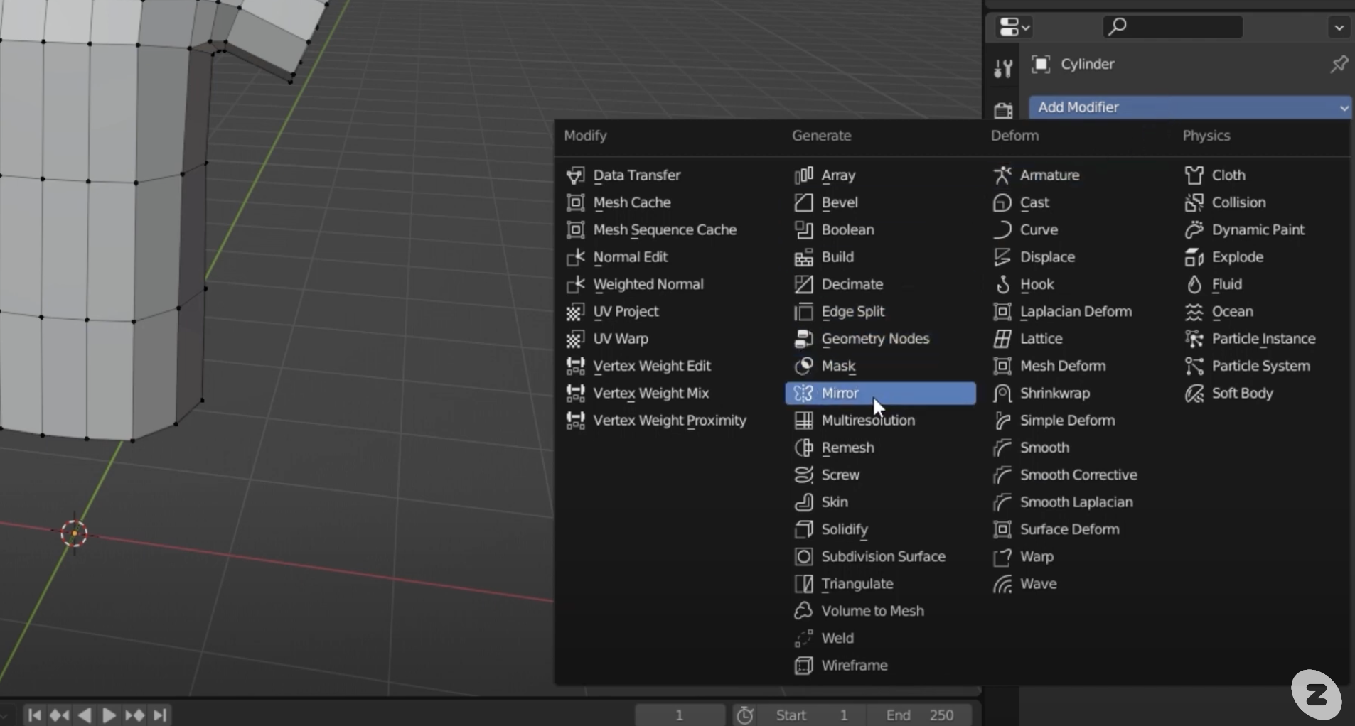
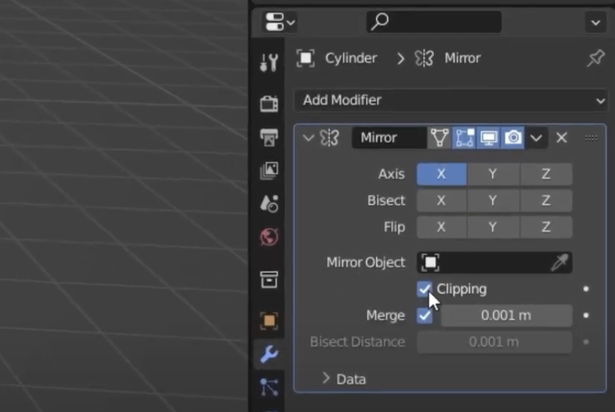
- Select Add modifer > Mirror. You'll see your object mirrored across the object, centered on the X-axis.
- In this state, the original object you created exists alongside the new, uneditable part.
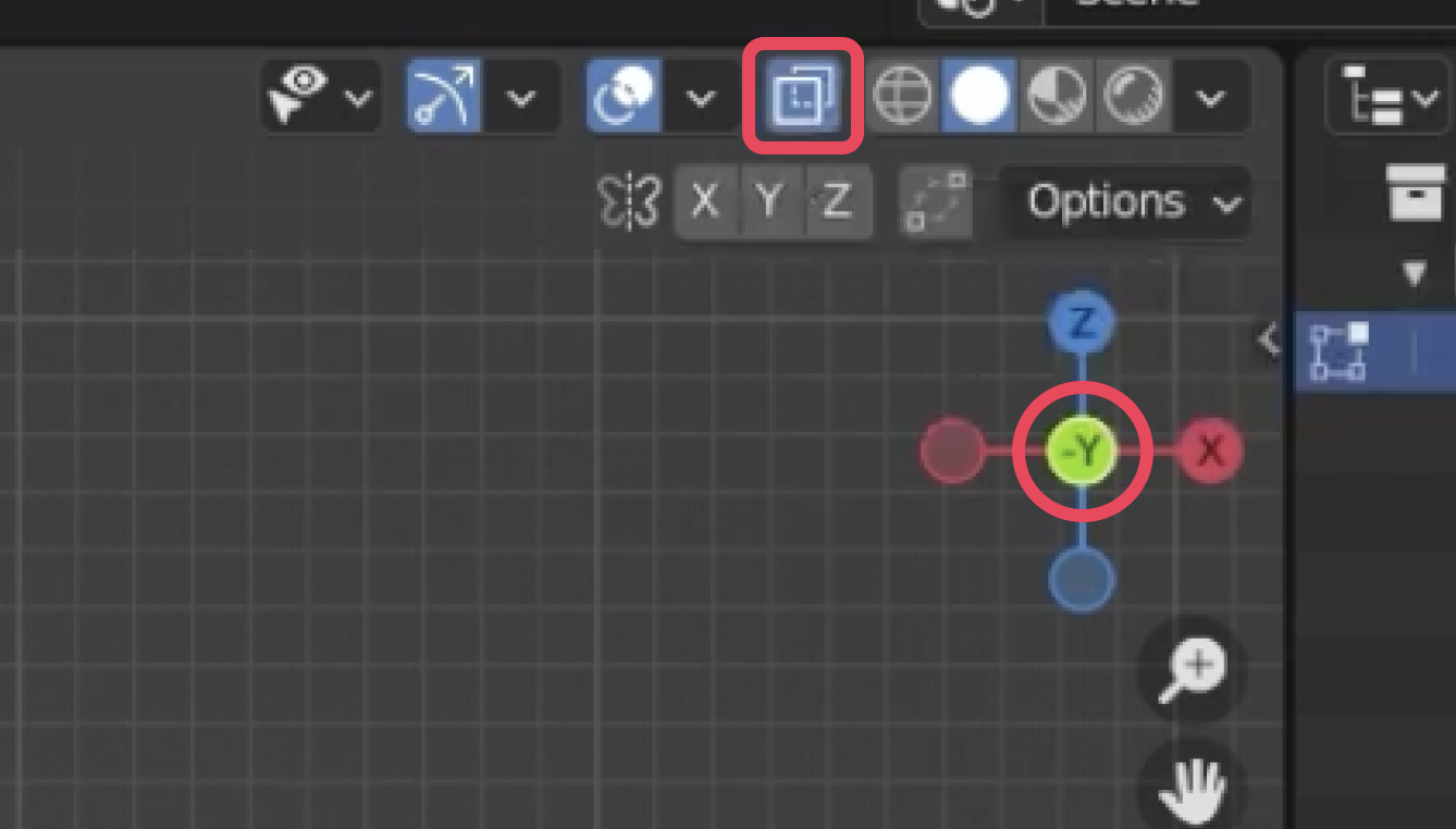
- To effectively use mirror mode, we need to cut the object in half because we only need to work on one side.
- Using something like Gizmo, select the mesh for the other half, excluding the center edge loop.
- In the Mirror Modifier properties, select the Clipping checkbox. This will ensure that the vertices do not cross the center line and fall off the center.
Shading options
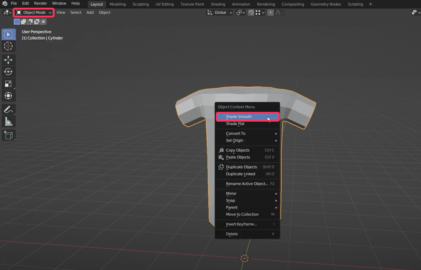
For organic shapes like fabric, it's best to use smooth shading.
- For shading options, right-click the object in Object Mode and select Shade smooth.
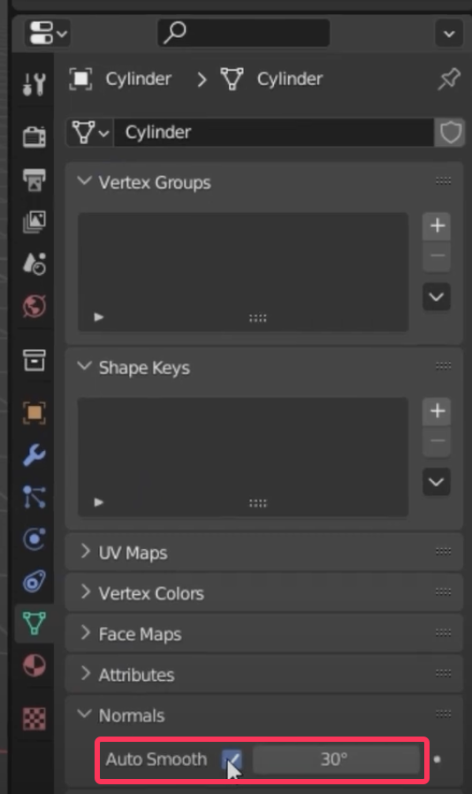
However, edges like collar and sleeves need to be automatically sharpened.
- Select the Object Data Properties icon, check Normals > Auto Smooth, and adjust the number. On average, 80 to 90 degrees is suitable.
STEP 4 : Prepare for Modeling
Creator Base Set
To create your ZEPETO item, you will need to reference the size and proportions of your avatar. Download the creatorBaseSet_ZEPETO.zip file from the Preparing for Modeling guide.
Importing
- Import the creatorBaseSet file you downloaded earlier into Blender. Before doing so, delete all objects on the screen with the keyboard hotkey X, including lights and cameras.
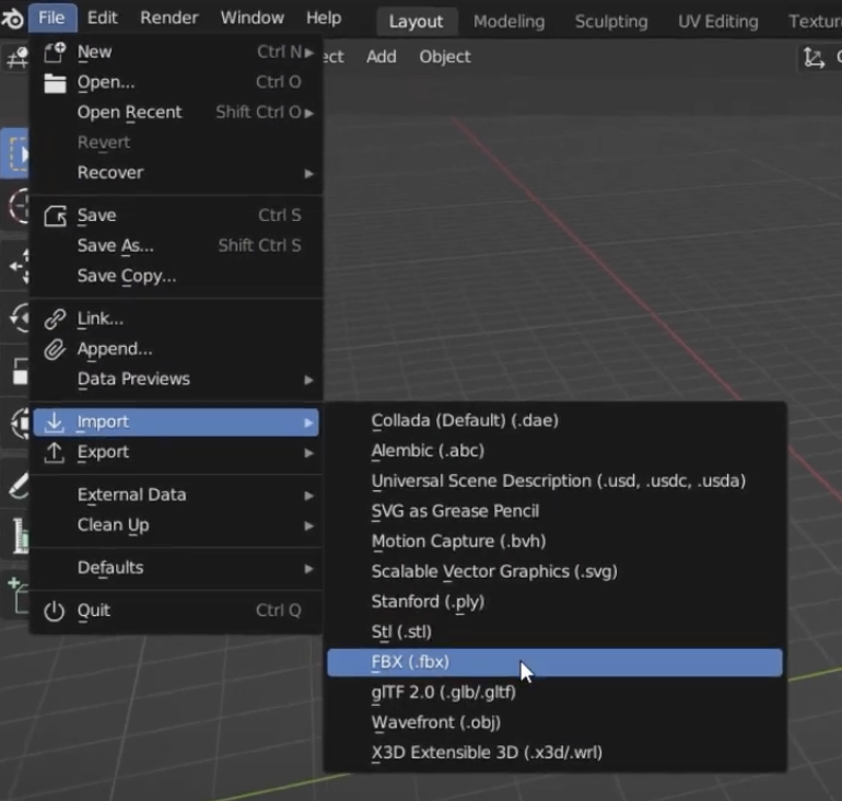
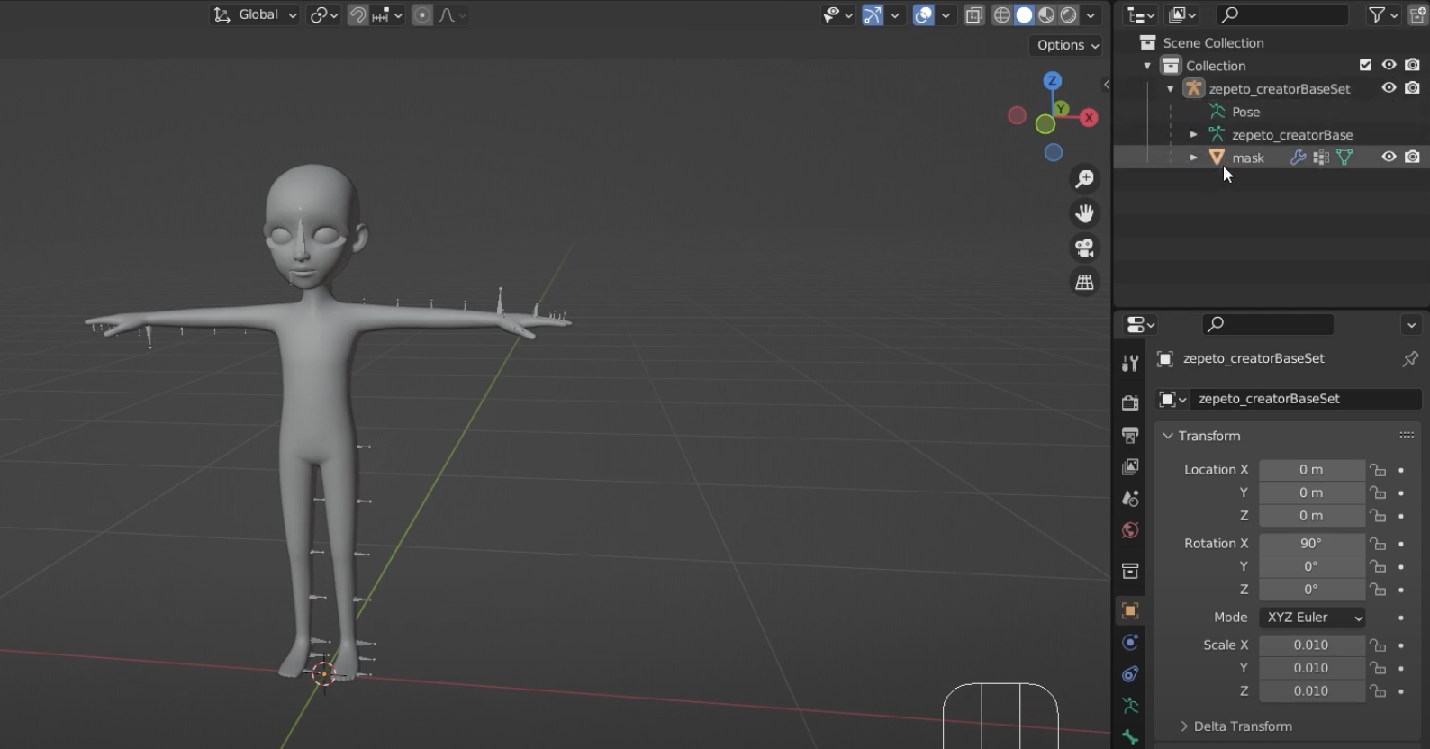
- Import the file by going to File > Import > FBX and the ZEPETO character will appear on the screen.
- The creatorBaseSet file contains the skeleton and mask for the ZEPETO character.
A Pose
The character in the creatorBaseSet file is imported in a T pose by default. The T pose is a standard pose used in 3D modeling software. For creating clothing items, it is more convenient to work in A pose than T pose.
- To set the character in A pose, you will need to rotate the shoulders and upper arms on the creatorBaseSet skeleton. To make things easier, set a separate rotation base instead of Blender's default rotation vector.
- With the skeleton selected, change to Pose Mode and select Pose Properties.
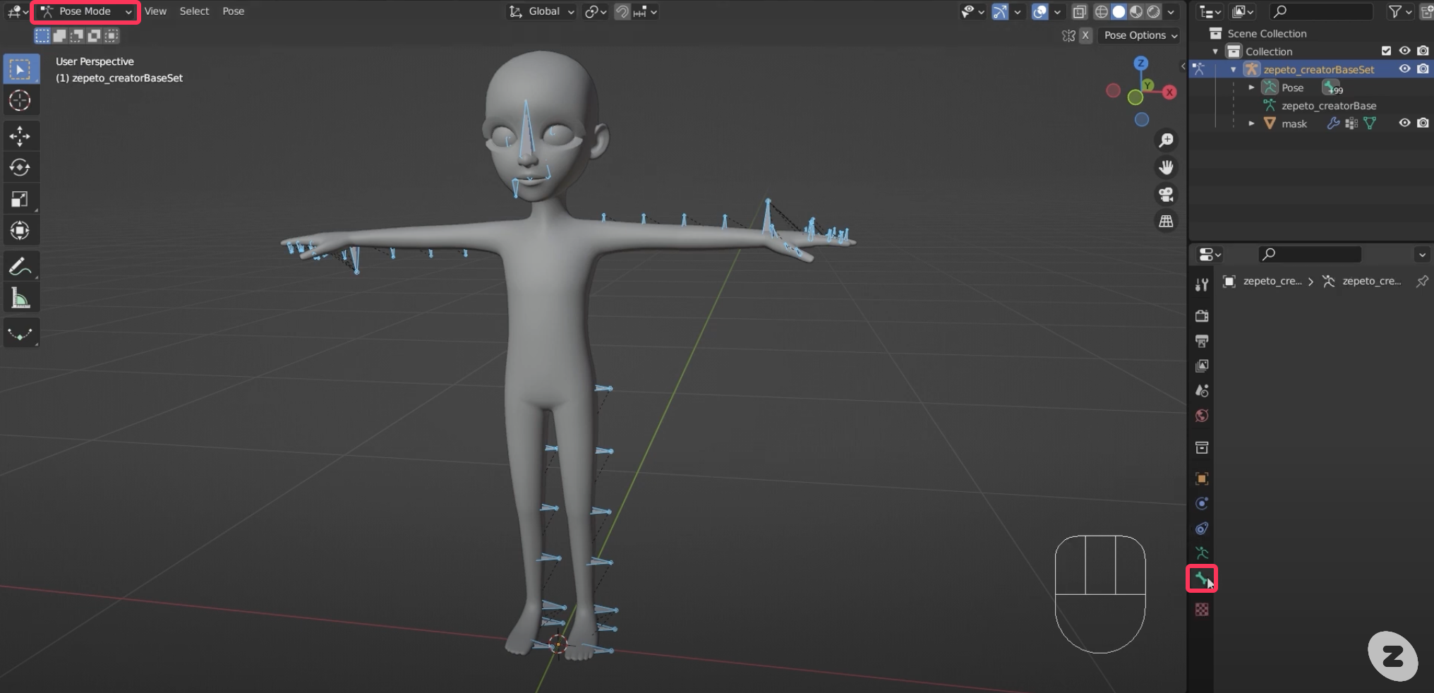
- If nothing appears in the Pose Properties tab, activate the skeleton by pressing the Shift key and selecting one of the bones in the skeleton.
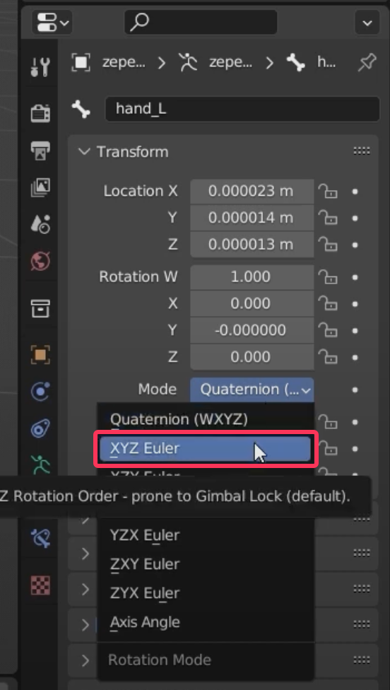
- When the skeleton is active and Transform appears, hold down the Alt keyand select the Mode drop-down menu. At the bottom, select XYZ Euler to change the rotation base.
- In the Outliner, with both shoulder_L and R selected, press the Alt key and select the Transform > Rotation Z property below, then type -7.5 and press Enter.
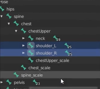
- In the Outliner, with both upperArm_L and R selected, press the Alt key and select the Transform > Rotation Z property below, then type -40 and press Enter. This will put the character in an A pose, as shown below.
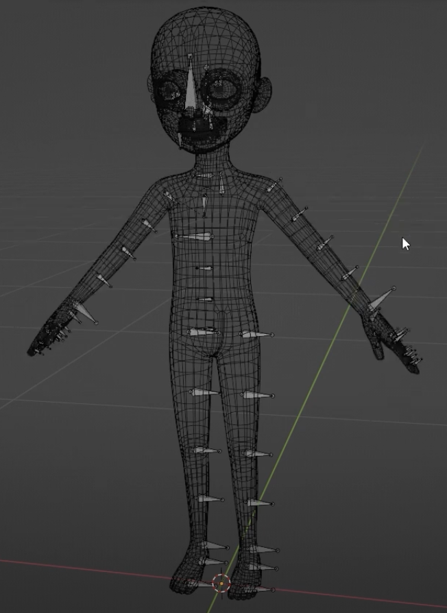
- You can now use this character as a mannequin of sorts to create costume items.
It's helpful to have a reference image to refer to when creating your items. Don't forget to save them periodically!
Updated 4 months ago